Overview
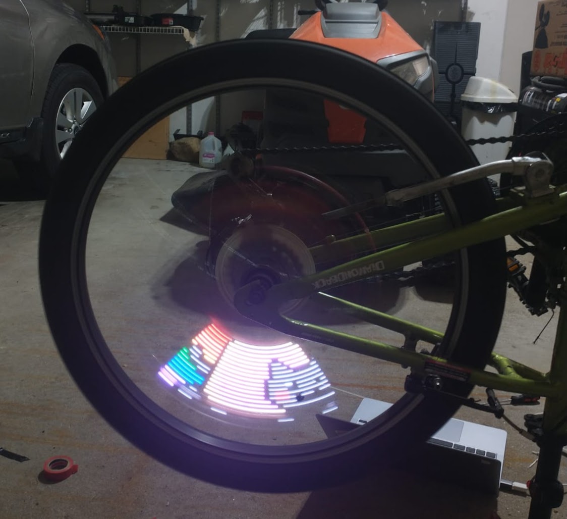
POV stands for Persistance Of Vision. Have you ever seen those fans that display the time when they spin? Thats an example. Our eyes can only see so much at once, and because of the speed of rotation, we are tricked into seeing a big picture. In actuality, there is only 1 row of lights, changing super rapidly to correctly display the picture.
Now, Imaging instead of a fan, the lights are on a bike wheel. The spin of the bikewheel is what creates the illusion. Naturally, this does create a few challanges to overcome, but this proved to be a fun project.
Since this project is still a work in progress, a full tutorial is not yet available. Please check out the blog for more information on what ive done/used so far.
05/17/2022
When I first began my research, I discovered that adafruit had already beaten me to the POV bike wheel idea, and came out with their own tutorial.
Their project was a helpful start, but there were things I wanted to add/change:
-
I want to display the whole image on the bikewheel, instead of just a small recurring image
-
I want to use 2 LED strips instead of one, so I dont have to pedal at Ludacris speed to see the image (Sorry Dark Helmet )
Of course these new ideas pose an added challenge, mainly that the Bike wheel is not spinning at a constant rate. This is why I need a way to measure the angular speed.
To mesure angular momentum, I got an mpu6050 6 axis gyroscope and accelerometer. These things are small and cheap, but effective. For the primary board, im using the adafruit pro trinket. THIS WAS A MISTAKE. Although the guide says to use this board, it is quite outdated. I recommend using the itsy bitsyU4 instead. It is about the same price and size, and has native USB on board. It has the ability to print to the serial monitor, which the pro trinket cant do. So debugging would be much easier. I am continuing to work with this board however, because I dont want to buy a new one.
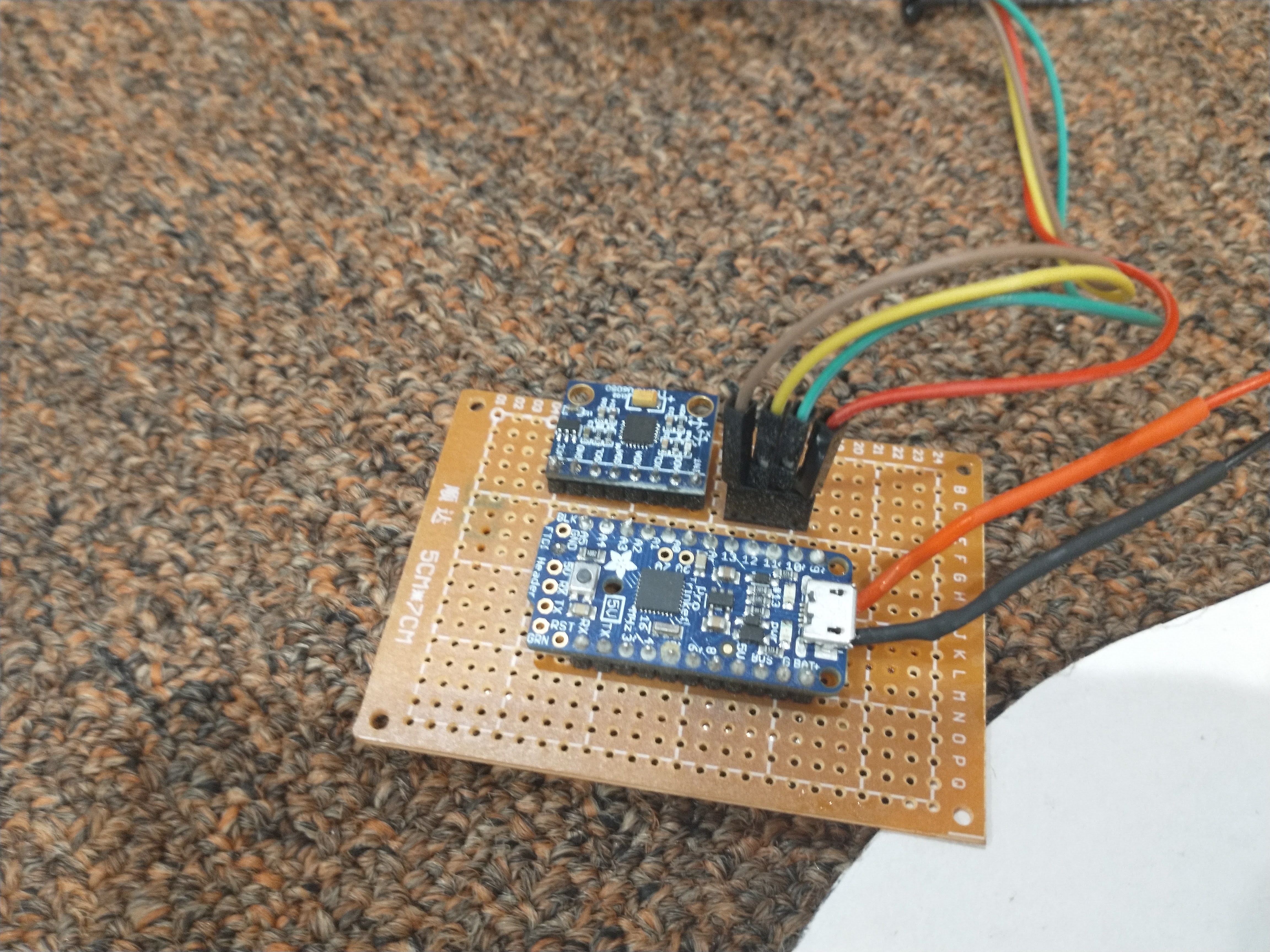
Image conversion:
The way adafruit programmed it, each vertical line in an image is displayed one after another. This works for recurring images or patterns, but if we want to fill the entire bike with one image, we have to get creative. I felt like changing the code itself would be a bit more challenging, so I opted for a different approach: changing the way the image itself looks. We have to make it so that each rotation displays the correct part of the image, and to do that, we use good ol trigonometry.
If you are not familiar with the polar coordinate system, let me explain. In polar coordinates, we have r and theta. R represents the radius. Each circle that we go out, we increase the radius by 1 unit. Theta represents the degrees rotated from standard position counter clockwise.
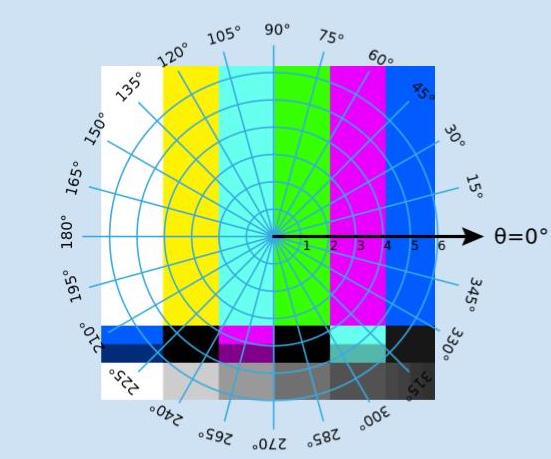
My goal here is to create a cartesian grid where each row represents an r(which will translate to each light on the strip), and each column will represent every 2 degrees change in theta. I chose 2 degrees because it yields pretty accurate results without taking up too much storage space.
To get the position of the polar coordinate in the image matrix, we use the equation:
imageArray[offset+r*sine(theta)][offset+r*cos(theta)]
Where offset is equal to half the width of the image minus 1 in pixels.
Confused? Its ok, i'll do the math for you this time ;)
Here are a few conversion examples


Although in theory everything should work, in practice it hasn't been doing exactly what I had hoped. When spinning, the image seems to be slowly rotating with every rotation of the wheel. It is possible that the accelerometer/gyroscope wasn't the best fit for the project. I will be researching other methods of recording angular momentum.
07/25/22
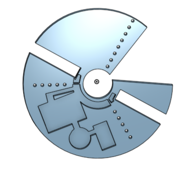
I have made a few 3d models in onshape to keep the build all together, and make it easy to remove.
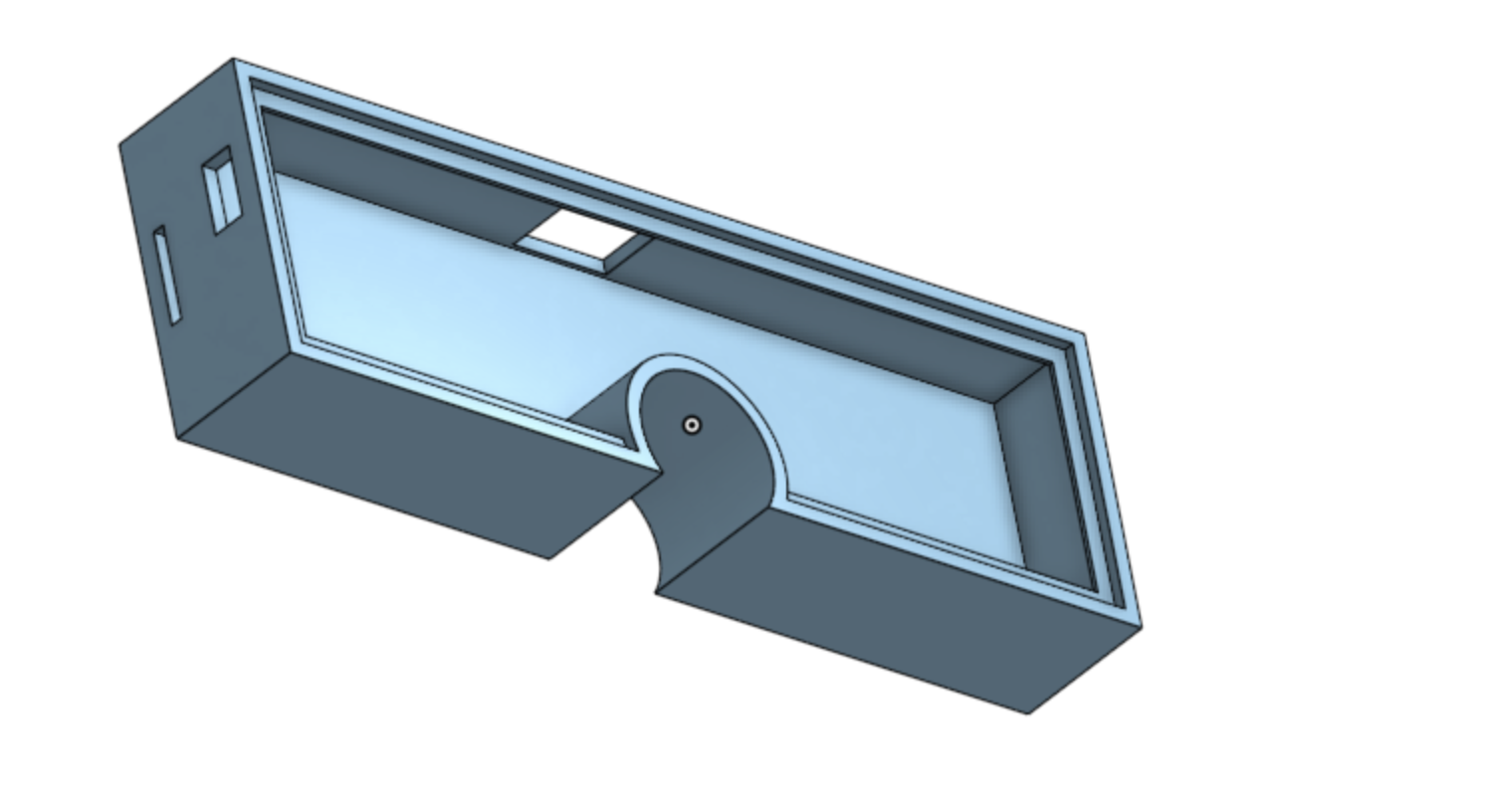
Additionally, I have decided to use a hall effects sensor instead of an accelerometer.
A Hall effects sensor detects strong magnetic fields, and sends a pulse to the board. I will place a magnet on the brace of my bike right next to the wheel. Whenever the hall effects sensor mounted on the board passes the magnet, it notes that 1 revolution has been made. It then divides the amount of time between each revolution and divides it by 90 to get the delay between each image line.
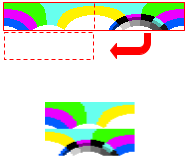
For the polar conversion code, I added an option for the radius of the hole in the middle of the image. Since the led strip isnt starting in the exact center of the bike wheel, it will have a hole, and all the pixels need to be offset. Additionally, I added a feature for when there are two strips on the bike wheel. The code simply splits the converted image in half and then stacks it like this:
07/30/22
So far testing has been increadibly difficult. Every time I want to change something, I have to plug the board into my computer, upload the code, unplug it, plug the board into the battery, and then spin the wheel by hand. Although this may not seem too bad, it makes it really hard to periodically check minor details in the code. Furthermore, the adafruit trinket can not print to a serial monitor, so I have no idea whats going on code wise.
Current Setup:
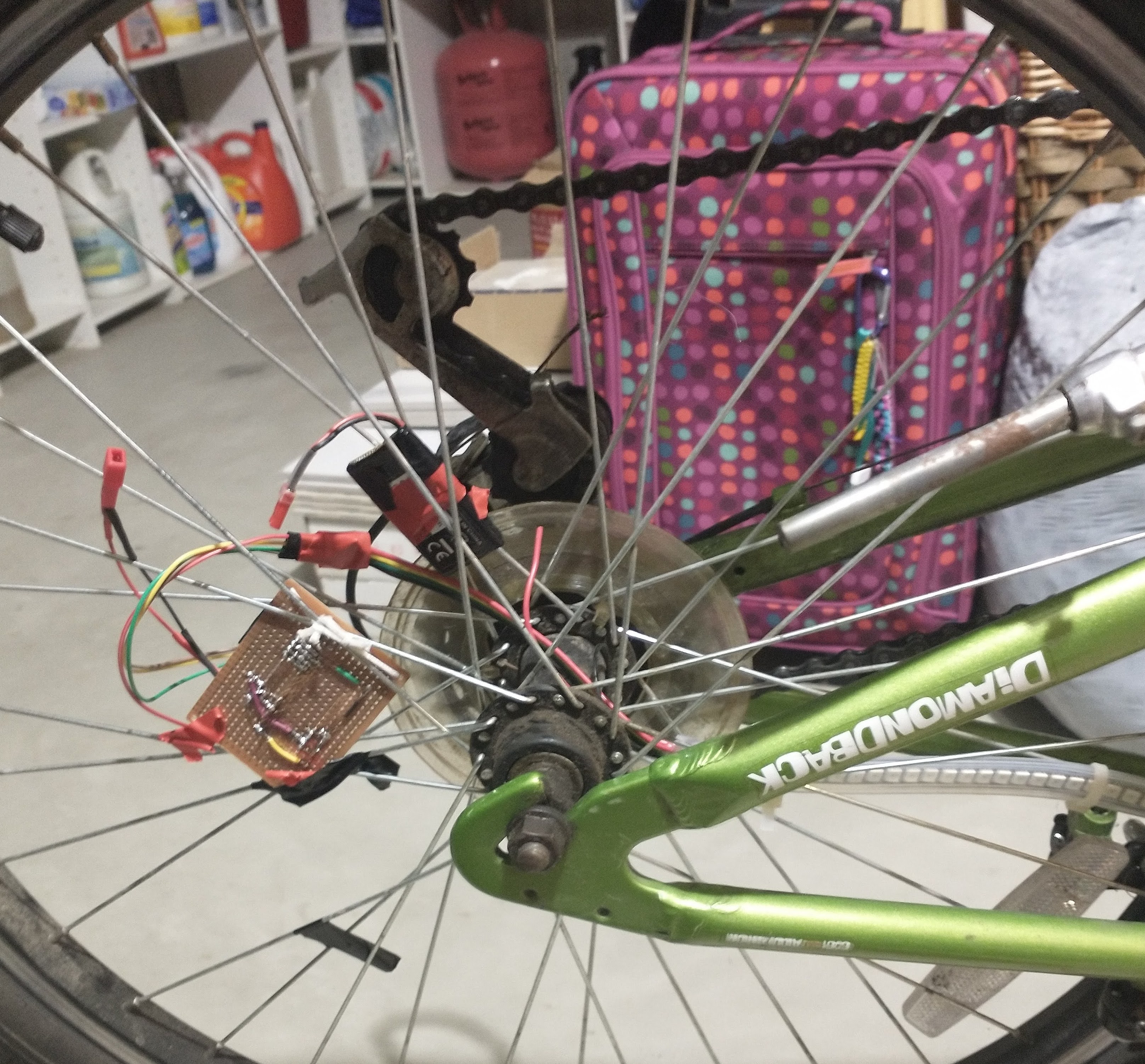
I have noticed that the image is still slightly rotating after each iteration, and im not positive why. I made sure the image is being remade correctly, and the hal effects sensore seems to be accuratley picking up the passing of the magnet. This most likley leaves it to a timer error in my code. I will look into possible ways of simulating my code with a visual outcome.